01The Problem in Leon, Iloilo
In our household in Leon, Iloilo, our daily water supply relies on a 1.5 horsepower deep-well pump that draws ground water into a 660-liter elevated storage tank. Deep-well pumps of this size are sensitive, high-current inductive equipment:
- Dry-Run Cavitation: If the groundwater table drops during the dry season or the suction pipe draws air, the impeller spins without water lubrication. Running dry for even 2–3 minutes overheats the motor bearings and permanently burns out the windings.
- Manual Inconvenience: Family members had to climb to check tank levels visually, manually flip breakers, and estimate when the tank was full. Forgetting to turn the pump off led to tank overflows and wasted power.
- Off-the-shelf Switch Failures: Standard consumer Wi-Fi smart plugs use low-grade mechanical relays. Inductive arcing from switching a 1.5 HP motor welds relay contacts closed in weeks, leaving the pump continuously energized.
02Physical & Environmental Constraints
Engineering a reliable solution required addressing practical physical obstacles on the ground:
40-Meter Separation
The overhead water tank is located 40 meters away from the pump motor shed, separated by concrete exterior walls and trees. Direct 2.4 GHz Wi-Fi between the nodes was unstable, particularly during heavy tropical rainstorms and typhoon seasons.
Severe Electrical Noise (EMI)
When a 1.5 HP single-phase motor starts and stops, massive inductive voltage spikes and electromagnetic noise are generated along adjacent conduit runs. Single-ended signaling wires instantly picked up false triggers.
03System Architecture & Hardware Topology
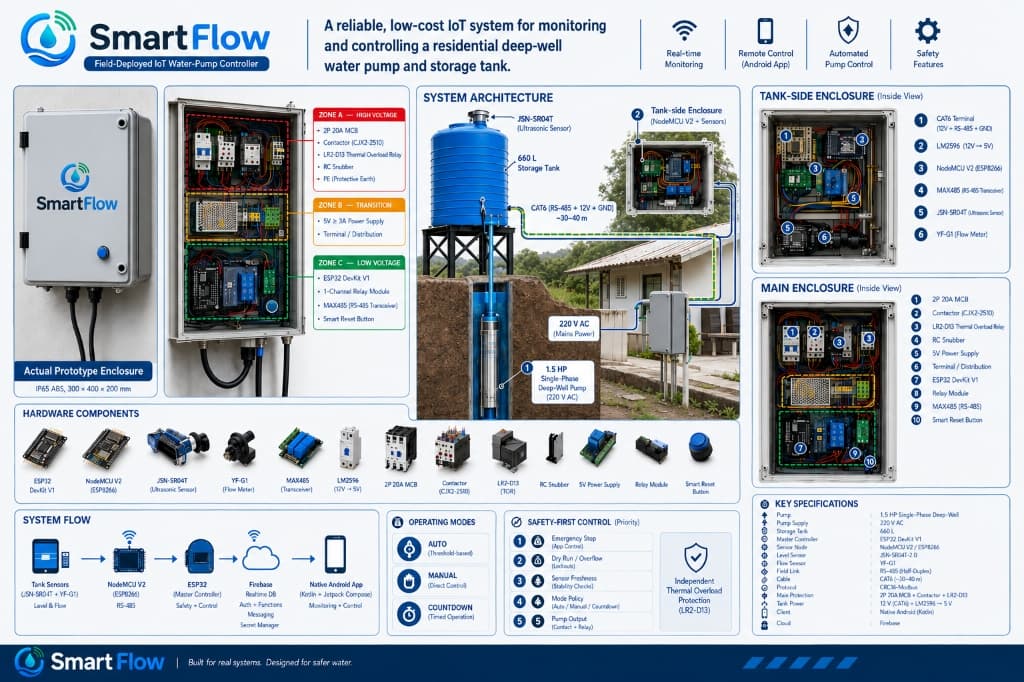
To solve the distance and noise challenges, I divided the system into two distinct computing nodes communicating over a physical differential bus:
Interactive Hardware Topology Diagram
Click any subsystem node to inspect its hardware components, wiring, and safety rules.
Master Controller Node (ESP32)
- ›Microcontroller: ESP32 (dual-core 240 MHz)
- ›Telemetry input: Hardware Serial2 with MAX485 transceiver
- ›Flow sensor: YF-G1 1-inch Hall-effect turbine meter on the discharge line
- ›Safety inputs: Normally closed hardware emergency stop button
- ›Actuation output: GPIO trigger to optoisolated relay driver
The brain of the system. Enforces local safety rules: 15-second dry-run lockout if flow meter pulses stay at zero, 45-minute continuous run ceiling, and automatic sensor jitter filtering.
Dual cores allow dedicated execution: Core 0 handles Wi-Fi, BLE, and cloud telemetry, while Core 1 handles real-time interrupt pulse counting and emergency contactor control without timing jitter.
The power chain is built with industrial switchgear: 220V grid AC feeds a Miniature Circuit Breaker (MCB), feeding the CJX2-2510 magnetic contactor and LR2-D13 thermal overload relay. The microcontroller never switches motor current directly—it only triggers the contactor coil through an optocoupler.
04Safety Gates & Firmware Fail-Safes
The core principle of SmartFlow is that safety decisions must always happen locally in firmware, regardless of whether the home internet or cloud connection is alive.
15-Second Dry-Run Lockout
Upon starting the pump, the ESP32 samples pulses from the YF-G1 1-inch flow meter. If zero flow pulses are recorded within 15 seconds, firmware immediately de-energizes the contactor, enters an error state, and logs a dry-run event.
Heartbeat & Stale Data Timeout
The tank node transmits telemetry frames every 2 seconds over RS-485 with CRC16 checksums. If the master ESP32 misses 5 consecutive frames (10 seconds), the pump automatically shuts down under an assumed wire break.
45-Minute Maximum Continuous Runtime
Even under healthy fill rates, the tank takes 20 minutes to fill from empty. A hard 45-minute watchdog timer cuts motor power to protect against broken downstream pipes or stuck sensor readings.
05Current Status & Known Boundaries
SmartFlow is installed inside an IP65 enclosure at my home in Leon, Iloilo. It has been operating daily under owner supervision.
• Not independently certified by third-party regulatory bodies.
• Not tested across diverse commercial installations or multi-phase power grids.
• Ultrasonic sensor readings experience minor jitter (±2 cm) during severe tropical condensation inside the tank lid.
06Lessons Learned & Future Improvements
Building SmartFlow taught me the stark difference between a clean breadboard demo on a workbench and a physical deployment that has to survive high voltages and tropical weather:
- Secondary Mechanical Interlock: Relying exclusively on an ultrasonic sensor means condensation can occasionally cause reflection false alarms. If rebuilding today, I would wire a mechanical float switch directly in series with the contactor coil circuit as a fail-safe cutoff.
- Custom PCB Over Protoboards: Hand-soldering point-to-point protoboard wiring inside an IP65 box took dozens of hours and increased maintenance effort. Designing a two-layer PCB with dedicated screw terminals and TVS surge diodes would significantly improve build robustness.